
Technology · Glossy, oily and metallic parts
3D vision for glossy, oily and metallic parts
Machined steel, oiled blanks, painted bumpers, film-wrapped packs: these are the parts where 3D cameras most often produce holes, noise and points that are not there. This guide explains why, how the common 3D methods cope, and how a light-field camera such as LumiScan X measures these surfaces reliably enough for a robot to pick them.
Why reflections disturb 3D measurement
Almost every 3D camera relies on the same assumption: a point on the part looks the same from every direction. That holds for matte surfaces, which scatter light diffusely. A glossy surface behaves more like a mirror. It sends most of the light in one direction, so what the camera sees depends on where the camera, the lamp and the part are – not only on the shape of the part.
Most industrial parts sit in between: machined or blasted steel has a broad glossy lobe, paint adds a sharp mirror reflection on top of the colour, and an oil film turns a rough surface into a smooth, shiny one. Four effects follow:
Saturated highlights
Where the reflection of a lamp falls into the camera, pixels saturate. There is no texture left to measure, so the point cloud has a hole.
Highlights that move
A reflection is not attached to the surface; it moves as the viewpoint changes. A method that matches features between two views can mistake it for a surface point and place it at the wrong depth – the “ghost points” the robot then tries to avoid.
Reflections between parts
In a full bin, light bounces from one part onto the next. Projected patterns and laser lines arrive where they were never aimed, and active sensors decode them as false depth.
Too little light back
Dark, polished metal scatters little diffuse light. Next to bright highlights, the dynamic range of one exposure is often not enough, and the dark areas drown in noise.
The 3D methods compared
No 3D method is immune to gloss. They fail in different ways – and some failure modes are easier to manage in a robot cell than others.
| Method | How it gets depth | On glossy, oily, metallic parts | Where it is strong |
|---|---|---|---|
| Passive stereo | matches texture between two views | highlights look different in the two views – false matches and holes | textured, matte scenes; low cost |
| Active stereo | a projected random pattern adds texture | on mirror-like areas the pattern is reflected past the camera; highlights saturate | matte, low-texture parts |
| Structured light / fringe projection | a sequence of coded patterns, phase decoding | reflections between parts corrupt the code; several exposures needed; the part must stand still during the sequence | high accuracy on static, diffuse parts |
| Laser triangulation | a camera sees the laser line at a known angle; part or sensor moves | reflections create secondary peaks; very dark and very bright returns; needs relative motion | high-resolution profiles, inline inspection |
| Time of flight | measures the travel time of light per pixel | multipath between parts and weak return from dark metal – depth bias and noise | large volumes, logistics, cartons |
| Deflectometry | evaluates a pattern mirrored in the surface | made for mirror-like surfaces; measures slope rather than pose, not for cluttered bins | surface defects on painted and polished panels |
| Light field | many simultaneous views, several baselines | view-dependent highlights do not fit all views and can be rejected; one exposure; pattern projector optional | glossy, metallic and film-wrapped parts in bins, moving parts |
How light field captures glossy surfaces
LumiScan X records the scene with 13 cameras that expose at the same moment. Each camera sees the part from a slightly different position, and several baselines – the distances between camera pairs – are available at once.
For a matte surface point, all 13 views agree: the point appears where the geometry says it should. A highlight does not follow that rule. It belongs to the reflection of the lamp, which sits at a different apparent depth, and it often shows up in only some of the views. Because the reconstruction checks each depth estimate against many views and baselines instead of a single pair, observations that do not fit are recognised and down-weighted instead of turning into ghost points.
Because all cameras expose simultaneously, there is no pattern sequence and no scanning motion: parts on a conveyor or a camera on a moving robot are captured in one shot. Where a part has no texture at all – a smooth, matte, single-colour surface – the optional LumiScan SL pattern projector adds artificial texture.
To be honest about it: light field is still triangulation. For every triangulating camera, depth uncertainty grows with the square of the distance (σZ ≈ Z² / (f · b) · σd). What the extra views buy is a smaller, more reliable σd – more independent observations of each point and fewer outliers. That is why working distance and field of view belong in every feasibility test.
Oily parts: what changes
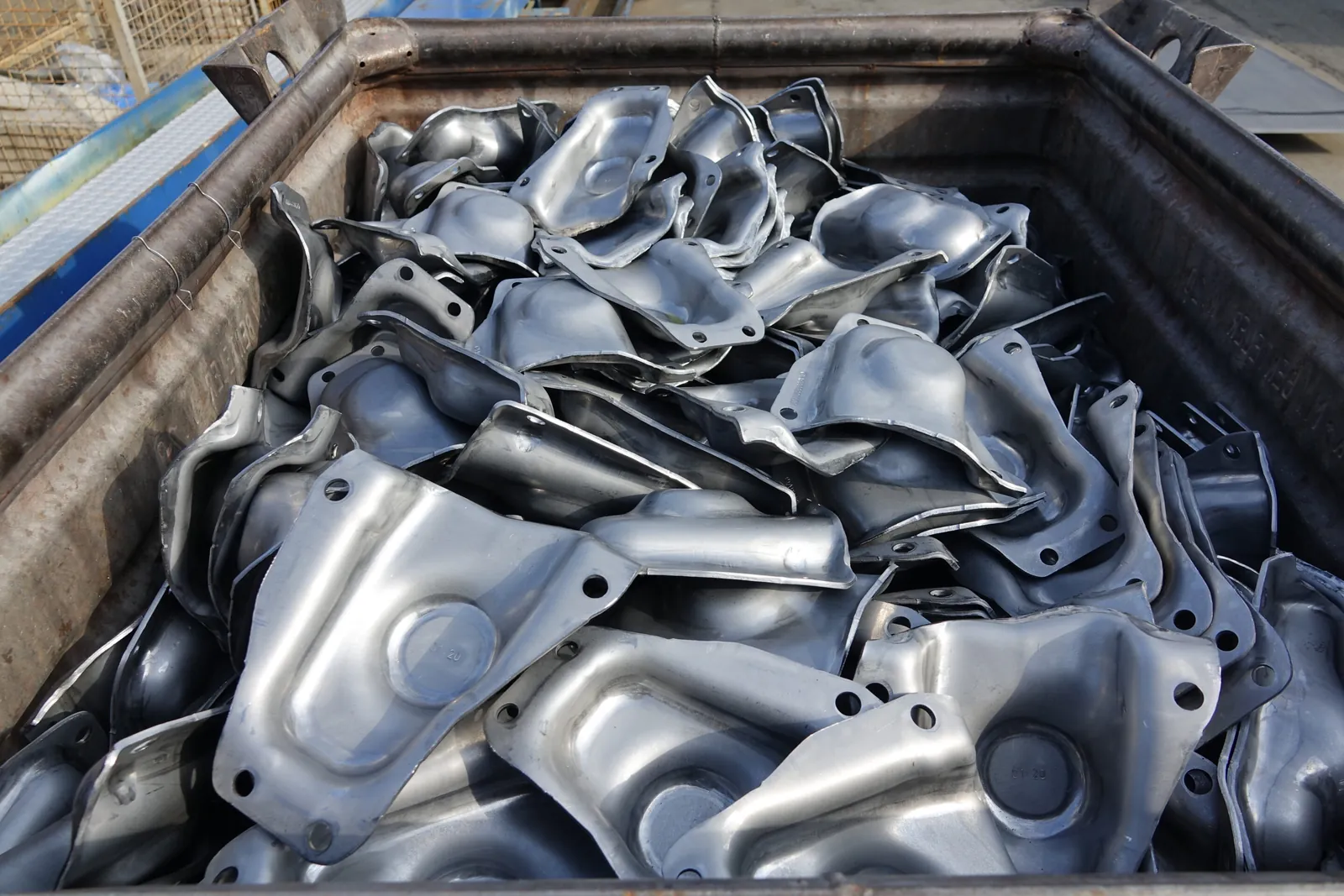
Oil is not a surface property you can put on a drawing. It varies from batch to batch, between the top and the bottom of a bin, and over a shift. A part that was matte after machining turns shiny as soon as it is oiled for corrosion protection, and drops collect on edges and in the corners of the bin.
- Test with parts as they really arrive – including the oiliest batch.
- Watch the bin floor: a shiny, uneven load carrier makes it harder to tell part from bin.
- Plan for the last parts in the bin, where reflections from the bin walls are strongest.
- Keep the camera window clean: oil mist settles on protective glass.
- Retrain the AI detection when the part condition changes – with LumiScan Annotation Framework and Training Framework that stays in-house.
Engineering the cell: light, exposure, mounting
Good 3D data on reflective parts starts before the software. Four levers matter most:
Control the light
An enclosure or booth takes changing daylight and hall lighting out of the equation. Mühlbauer’s bumper inspection systems use closed booths for exactly that reason.
Mind the mirror geometry
Do not place lamps where their reflection points straight into the camera. Diffuse light spreads highlights over a larger, weaker area.
Several exposures where needed
Merging several images extends the dynamic range for parts that are bright and dark at the same time.
Choose the mounting
Fixed above the bin is faster; on the robot, the camera can take a second look from another angle when a part is ambiguous.
From point cloud to grasp
A clean point cloud is only useful if the software turns it into a safe robot motion. In the LumiScan Vision Suite, that is done by apps you combine:
- LumiScan VGR
- locates parts CAD-based or AI-based, computes grasp points and plans collision-free paths into the bin and back out.
- LumiScan VGR Lite
- the same collision checking and path planning with purely AI-based detection – no CAD model needed.
- LumiScan AI Object Matching
- recognises parts without a CAD model.
- LumiScan Annotation Framework
- annotates your own images – including glossy and oily parts at every fill level.
- LumiScan Training Framework
- trains ONNX networks from them for the runtime apps.
The LumiScan Vision Suite runs on Windows 11, Ubuntu 24.04 and Bosch Rexroth ctrlX OS; LumiScan VGR and VGR Lite currently run on Windows 11.
In production
Three projects with exactly the surfaces this guide is about:
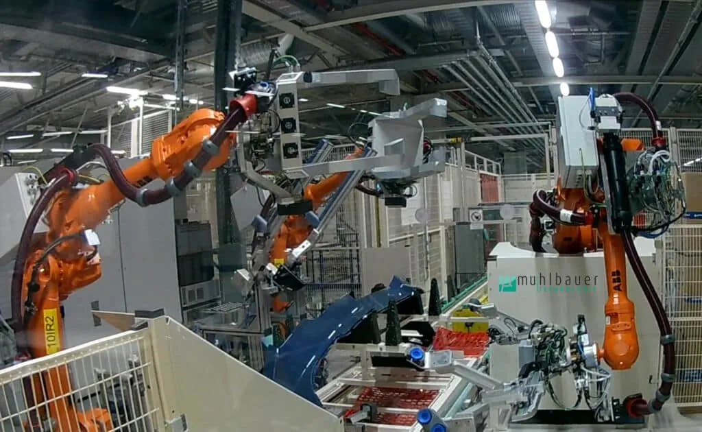
Inspecting glossy bumpers with light field and LumiScan VGR
Painted, glossy bumpers: two LumiScanX and two pattern projectors per system; for highly reflective and dark parts, several images are merged.
Read the case study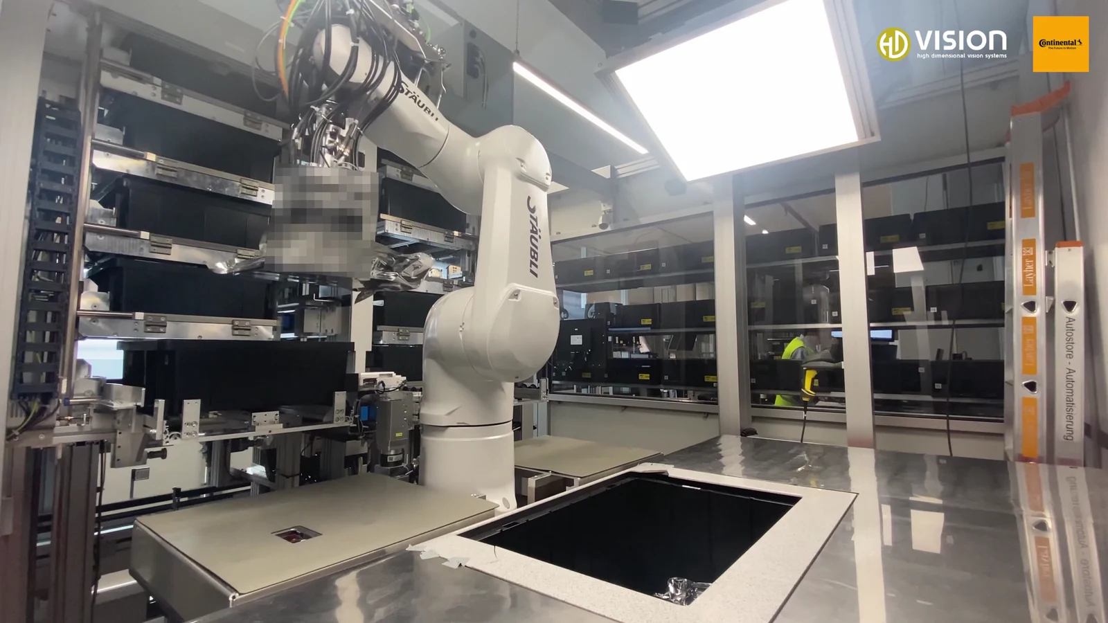
Picking SMD reels and PCB packs from an AutoStore automatically
Vacuum-sealed PCB packs and shrink-wrapped SMD reels whose films reflect – picked straight at the AutoStore port.
Read the case study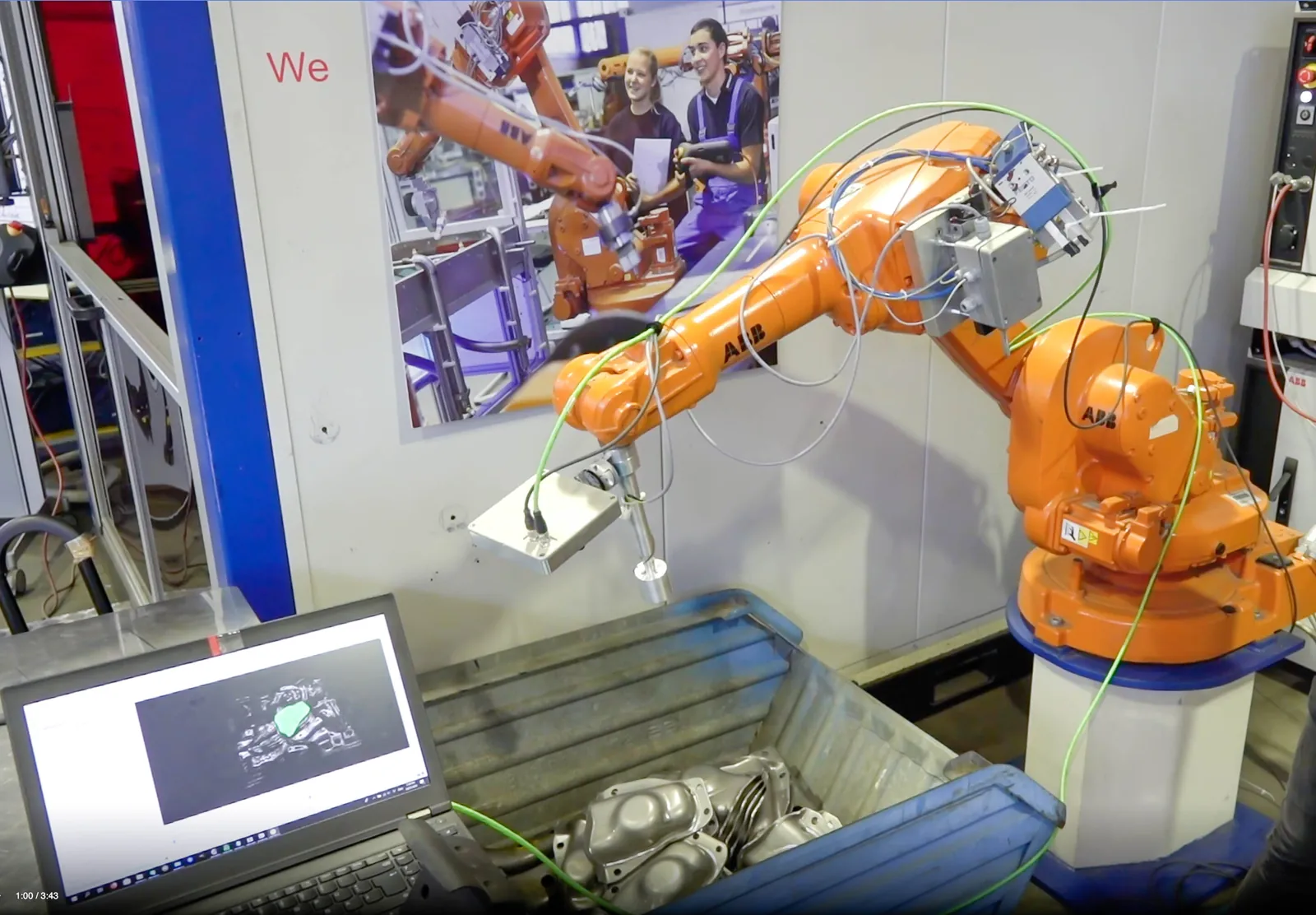
Bin picking oily steel parts from mixed boxes
Oily, shiny steel parts from unsorted boxes with an uneven floor – trialled at the test centre.
Read the case studyTest with your own parts
Whether a camera captures a glossy part reliably is, in the end, shown only by a test with real parts. To make the test meaningful:
- Send the hardest parts, not the nicest: the oiliest batch, freshly machined and aged surfaces.
- Include the real load carrier – the bin floor and walls reflect too.
- Test full, half-full and nearly empty bins.
- Agree beforehand on what counts: detection rate, pose accuracy derived from the gripper tolerance, cycle time.
- State working distance, mounting position and ambient light of the future cell.
HD Vision Systems supplies the camera, lighting hardware and LumiScan software; the cell is built by your automation supplier or an integration partner. We carry out a feasibility study on request.
All articles on glossy and metallic parts
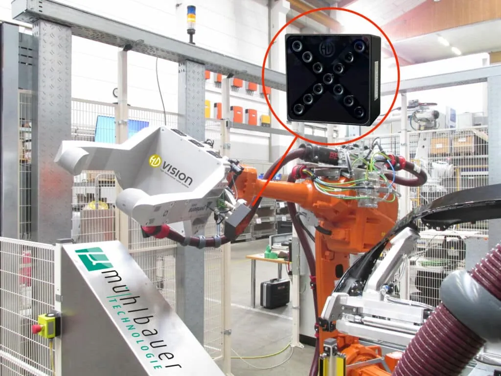
Why shiny parts fool 3D cameras – and what helps
Highlights that saturate, reflections that move with the viewpoint, light bouncing between parts: the physics behind holes and ghost points in 3D data of glossy and metallic parts.
3D sensing methods for reflective parts compared: stereo, structured light, laser, ToF and light field
How passive and active stereo, fringe projection, laser triangulation, time of flight, deflectometry and light field cope with glossy, oily and metallic parts – and when to combine them.
Bin picking oily metal parts: what changes when there is an oil film
Oil makes metal shiny, varies from batch to batch and collects in the bin. What that means for 3D vision, detection, grasping and maintenance in a bin-picking cell.
Lighting and exposure for 3D vision on reflective parts: a practical guide
Mirror geometry, enclosures, diffuse light, polarisation, filters, multiple exposures and projected texture: what really helps a 3D camera on glossy and metallic parts.
Testing glossy parts before you invest: a feasibility checklist
Which samples to send, how to define success, what to tell us about the cell – and what you get back. A checklist for testing 3D vision on glossy, oily and metallic parts.
Why light field? What a multi-view camera adds in machine vision
A light-field camera records a scene from many viewpoints at once. What that adds for glossy parts, occlusions and moving objects – and where the physics sets limits.
Laser triangulation vs. light field: which 3D method for which part?
How laser triangulation and light-field cameras get depth, how each copes with glossy and metallic parts, where each is strong – and why the best cells often combine both.
Light field and structured light: different principles – and when to combine them
Structured light projects patterns, a light-field camera records many views at once. How both work, how they cope with glossy parts, and why projected texture and light field go well together.