3D sensing methods for reflective parts compared: stereo, structured light, laser, ToF and light field
This comparison looks at the common 3D methods one by one: how they get depth, what goes wrong on reflective surfaces and where each one is the right choice.
The physics behind the failure modes – saturated highlights, reflections that move with the viewpoint, light bouncing between parts, and too little diffuse light – is explained in Why shiny parts fool 3D cameras. The overview of the whole topic is our guide 3D vision for glossy, oily and metallic parts.
Passive stereo
Principle. Two cameras a known distance apart. The software finds the same feature in both images; the shift between them – the disparity – gives the depth.
On reflective parts. Stereo needs texture that looks the same from both cameras. A highlight does not: it appears at different places in the two images or only in one. The result is false matches (ghost points) or no match at all (holes). With only two views, there is little redundancy to tell a highlight from a surface feature.
What helps. Diffuse lighting, a larger share of textured surface, careful placement of lamps.
Right choice for textured, matte scenes where cost matters more than robustness.
Active stereo
Principle. Stereo plus a projector that casts a random dot or speckle pattern, so that even featureless surfaces offer something to match. Works in a single shot.
On reflective parts. On matte areas the pattern helps a lot. On glossy areas the projected dots are mirrored away from the cameras – they simply are not seen – while the projector’s own reflection creates a bright highlight. Interreflections spread the pattern onto neighbouring parts.
Right choice for matte, low-texture parts such as cartons, castings and plastic housings.
Structured light and fringe projection
Principle. A projector casts a sequence of coded patterns – binary codes, sinusoidal fringes – and a camera decodes for each pixel which projector ray hit it. Very accurate on diffuse, static surfaces.
On reflective parts. The decoding assumes each pixel sees light from one projector ray. Interreflections break that assumption: a pixel receives light from two or more rays and decodes a wrong depth. Highlights saturate. Because the method needs several patterns in sequence, the part and the sensor must stand still during the whole sequence.
What helps. Multiple exposures, adapted pattern frequencies, polarisation filters, careful angles – all of which add time and tuning.
Right choice for high-accuracy measurement of static, mostly diffuse parts. A deeper look: Light field and structured light.
Laser triangulation
Principle. A laser line is projected onto the part and a camera at a known angle observes it. Each image gives one height profile; moving the part or the sensor builds up the 3D surface.
On reflective parts. A shiny surface reflects the laser line mainly in one direction. Depending on the angle, the camera sees almost nothing or a saturated line – and secondary reflections create extra peaks that the evaluation can mistake for the real line. Behind high edges the line is shadowed. Rough surfaces add speckle.
What helps. Choosing the angle between laser and camera, exposure control, peak-selection algorithms, two camera heads against shadowing.
Right choice for high-resolution profiles of parts moving past the sensor – inline inspection, weld seams, gap and flush. A deeper look: Laser triangulation vs. light field.
Time of flight
Principle. The sensor emits modulated or pulsed light and measures, per pixel, how long it takes to come back.
On reflective parts. Dark metal returns little light, so the signal is weak and noisy. Light that bounces between parts before returning travels a longer path and biases the depth – typically the corners of a bin and the gaps between parts look deeper or rounder than they are. Highlights saturate pixels.
Right choice for large volumes at moderate accuracy: logistics, cartons, people and pallet detection.
Deflectometry
Principle. The camera looks at the reflection of a known pattern – usually on a screen – in the surface. Distortions of the mirrored pattern reveal the surface slope.
On reflective parts. This is the one method that is made for mirror-like surfaces. But it measures slope rather than position, needs a defined geometry between screen, part and camera, and does not cope with cluttered bins.
Right choice for surface defect inspection on painted car bodies, glass and polished panels.
Light field
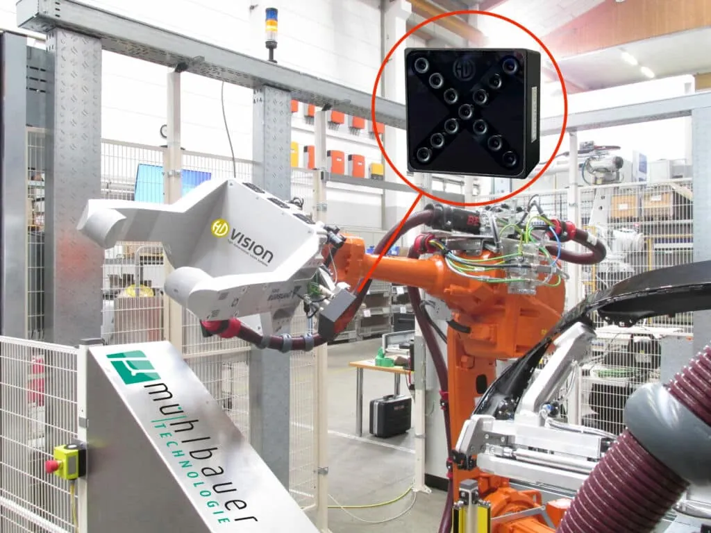
Principle. Many cameras – 13 in LumiScan X – record the scene simultaneously from slightly different positions. Depth is computed from the disparity across all views, using several baselines at once.
On reflective parts. A real surface point appears consistently across all views. A highlight does not: it moves with the viewpoint and often appears in only some of the views. Because every depth estimate is checked against many views instead of one pair, inconsistent observations can be rejected rather than becoming ghost points. One exposure captures everything, so moving parts and robot-mounted cameras are no problem. For matte, featureless areas, the optional LumiScan SL projector adds texture.
Limits. Light field is still triangulation, so depth uncertainty grows with the square of the distance; the extra views reduce noise and outliers but do not change the physics. Near-perfect mirrors remain difficult, as for every camera that relies on scattered light. The 13 images need GPU computing power.
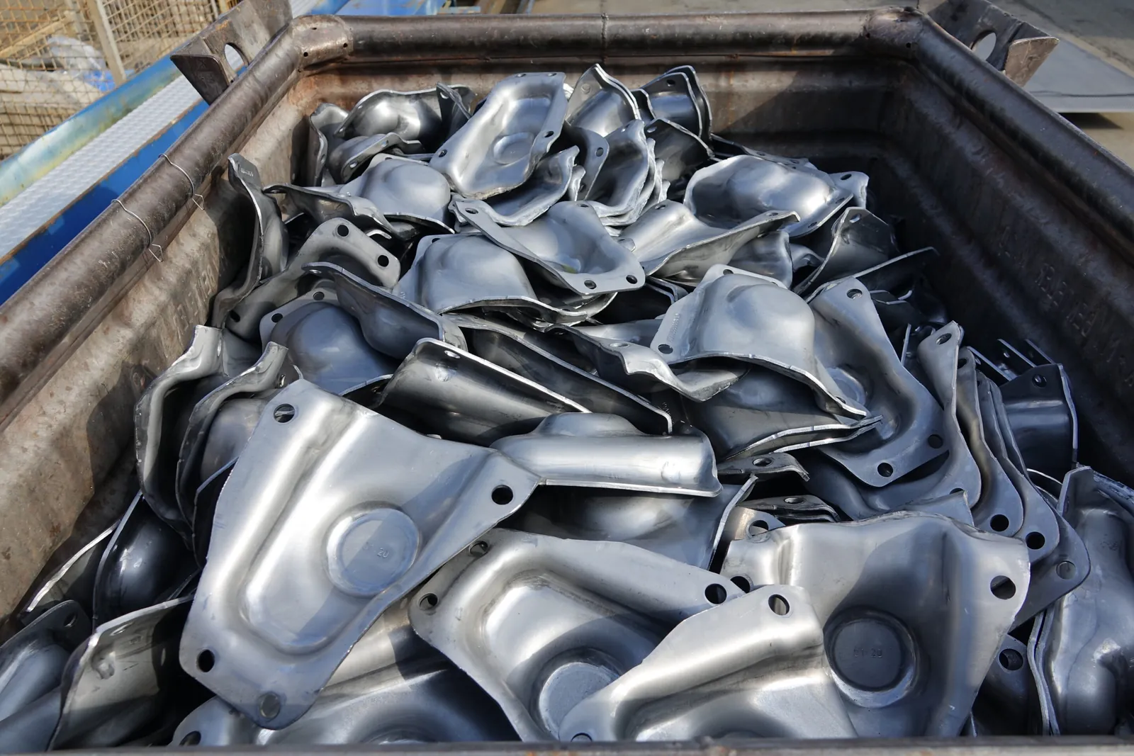
Right choice for glossy, metallic and film-wrapped parts in bins, on conveyors and on the robot – such as painted bumpers, vacuum-sealed PCBs and SMD reels and oily steel parts.
Summary
| Method | Single shot | Gloss: main problem | Interreflections | Typical use |
|---|---|---|---|---|
| Passive stereo | yes | false matches, holes | moderate | matte, textured scenes |
| Active stereo | yes | pattern mirrored away | moderate | matte, low-texture parts |
| Fringe projection | no | wrong decoding, saturation | strong | accurate static measurement |
| Laser triangulation | per profile, needs motion | dark or saturated line, secondary peaks | strong | inline profiles |
| Time of flight | yes | weak return, saturation | strong (depth bias) | large volumes, logistics |
| Deflectometry | no | – (made for mirrors) | – | surface defects |
| Light field | yes | inconsistent views are rejected | moderate | glossy parts in bins and in motion |
Combining methods
The best cell often uses two sensors for two jobs. The light-field camera finds the part and its pose in a cluttered scene; a laser profile sensor then measures a detail at high resolution along a path that the vision software has adapted to the real part position. This is how the visual clamping demonstration with Teledyne and the 3D inspection with an ABB PoWa cobot work. Because the LumiScan Vision Suite is hardware-agnostic, both sensors are configured and connected in the same software.
Which combination fits your parts is best answered with the parts themselves – see our feasibility checklist for glossy parts.
Frequently asked questions
Which 3D method is best for glossy metal parts?
There is no universal winner. For glossy parts in bins and parts in motion, light field is usually the most robust choice; for high-resolution profiles of parts moving past a sensor, laser triangulation; for surface defects on mirror-like panels, deflectometry. Many cells combine two methods.
Can structured light measure shiny parts?
Partly. It works where the surface still scatters enough light back to the camera. On mirror-like areas the pattern is reflected away, and in a bin, light bouncing between parts corrupts the decoding. Multiple exposures and polarisation help but cost time, and fringe projection needs the part to stand still.
Why does time of flight struggle with bins of metal parts?
Light that bounces between parts before it returns travels a longer path, so the sensor measures too great a depth – corners and gaps look deeper or rounder than they are. Dark metal also returns little light, which makes the signal noisy.
Is a light-field camera more accurate than a stereo camera?
Both triangulate, so for both the depth uncertainty grows with the square of the distance. A light-field camera uses many views and several baselines at once, which gives more observations per point and fewer outliers – in practice more complete and more robust data on reflective parts. Absolute accuracy depends on working distance, baseline and calibration.
Can I use two different 3D sensors in one cell?
Yes. A common pattern is to locate the part with a light-field camera and then measure a detail with a laser profile sensor along a path adapted to the real part position. The LumiScan Vision Suite is hardware-agnostic, so both sensors are set up in the same software.

PD Dr. Christoph Garbe
Christoph Garbe co-founded HD Vision Systems in 2017 and leads the company. As a Privatdozent (associate professor) at Heidelberg University (IWR), he heads a research group for image processing.