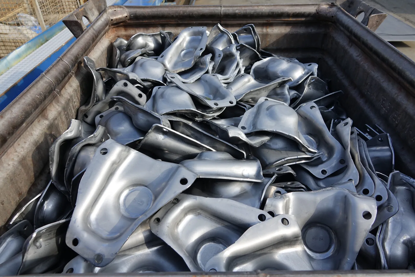
Why shiny parts fool 3D cameras – and what helps
Holes exactly where the surface is brightest and points hovering above the parts are rarely the fault of one particular camera – they are physics, and once you understand it, you can design the cell around it.
This article is part of our guide 3D vision for glossy, oily and metallic parts.
Two ways a surface returns light
A matte surface – paper, sandblasted aluminium, cardboard – scatters incoming light in all directions. Physicists call this diffuse or Lambertian reflection. Its useful property for machine vision: a point on the surface looks roughly the same from every viewing angle.
A mirror does the opposite. It sends the light in exactly one direction, angle of incidence equals angle of reflection. What a camera sees on a mirror is not the mirror itself but the reflected surroundings.
Real industrial parts sit in between. Their reflection has a diffuse part and a glossy lobe of varying width:
- Machined or ground steel has a broad lobe with a visible sheen along the machining marks.
- Paint and lacquer combine a diffuse colour layer with a sharp mirror reflection from the clear coat – the typical bumper.
- Oil films fill in the micro-roughness of a surface and turn a matte part into a shiny one.
- Films and foils – vacuum-sealed PCBs, shrink-wrapped reels – reflect like curved, wrinkled mirrors.
Almost every 3D method silently assumes the diffuse case: that a surface point can be recognised from different positions. The stronger the mirror component, the less that assumption holds. Four effects follow.
Effect 1: saturated highlights and missing data
Where the reflection of a lamp, a window or a bright hall light falls into the lens, the pixels saturate. In a saturated region there is no texture, no pattern and no gradient to measure. Whatever method you use, the point cloud gets a hole – often exactly on the flat top surface a vacuum gripper would like to use.
Effect 2: the highlight is not where the surface is
This is the subtle one. A reflection is not attached to the surface. On a flat mirror, the image of a lamp appears behind the surface, at the same distance as the lamp in front of it. On a convex part it moves closer to the surface, on a concave part it can float in front of it.
A stereo camera that matches a bright spot in its left and right image does not know that. It triangulates the virtual image of the lamp and places a point at that depth – below the part, inside it or in the air above it. These are the ghost points that make path planning treat free space as an obstacle, or worse, make a part look closer than it is.
The giveaway is that a highlight moves when the viewpoint moves, while a real surface point stays put. With two views, that is hard to check. With many views, it becomes a powerful test.
Effect 3: light bouncing between parts
In a bin of shiny parts, light does not stop at the first surface. It bounces from one part onto the neighbouring one, from the bin wall onto the parts, into concave features and back out. For passive cameras this mostly adds confusing highlights. For active sensors it is worse: a projected stripe pattern or laser line reaches places it was never aimed at, and the sensor decodes it as depth. Engineers call this multipath or interreflection, and it is the main reason why a sensor that works perfectly on a single part on a table struggles in a full bin.
Effect 4: too much and too little light at once
Dark, polished metal returns very little diffuse light – most of it goes into the mirror direction. Right next to a saturated highlight, the rest of the part is dark and noisy. The dynamic range of a single exposure is often not enough to capture both, so either the highlights saturate or the dark surfaces drown in noise.
What helps – in order of leverage
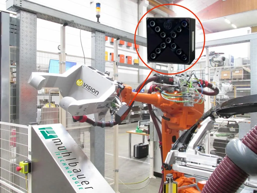
1. Look from more viewpoints. A highlight that appears at a different place in every view, or only in some views, can be recognised as inconsistent and down-weighted. This is the core advantage of a light-field camera such as LumiScan X: 13 cameras expose simultaneously and every depth estimate is checked against many views and several baselines, not a single pair. How the depth itself is computed is shown interactively on our technology page.
2. Control the light. Most highlights come from lamps and windows you could move or shield. An enclosure removes changing daylight and hall lighting; diffuse light spreads a sharp highlight into a broad, weak one. More in Lighting and exposure for 3D vision on reflective parts.
3. Extend the dynamic range. Several exposures merged into one image keep detail in highlights and in dark areas. In the Mühlbauer bumper inspection systems, several images are merged for highly reflective and dark parts.
4. Add texture only where it is missing. On matte, featureless surfaces a projected random pattern helps the cameras find correspondences. On glossy areas it helps much less, because the pattern is mirrored away. A projector is a tool for one problem, not a cure for gloss.
5. Make the software robust. Outlier filtering that keeps edges sharp (see how noise removal works), detection trained on images of your real parts, and collision checking that uses the cleaned data. Even a perfect point cloud needs software that turns it into a safe grasp.
The test that tells you more than any data sheet
No data sheet can tell you how a camera will see your parts under your light. A short test with the hardest samples – the oiliest batch, the darkest finish, the last parts in a nearly empty bin – tells you more than any specification. Our feasibility checklist for glossy parts lists what to send and what to agree on beforehand.
For a side-by-side view of how stereo, structured light, laser triangulation, time of flight and light field deal with these four effects, read 3D sensing methods for reflective parts compared.
Frequently asked questions
Why do shiny parts leave holes in a 3D point cloud?
Where the reflection of a lamp or window falls into the lens, the pixels saturate. A saturated region contains no texture, pattern or gradient to measure, so no depth can be computed there. Dark, polished areas next to it return so little diffuse light that their measurements are noisy and often filtered out as well.
What are ghost points?
Points that a 3D camera places where there is no surface. They appear when a reflection is matched between two views: the camera triangulates the mirror image of the light source, which lies behind, inside or in front of the part. Path planning then treats these points as obstacles or misjudges where the part really is.
Does a matting spray solve the problem?
In the lab, a temporary matting spray shows how the geometry of a part looks to a camera. In production it is rarely an option: it adds a process step and contaminates the part. The cell has to cope with the real surface.
Will a camera with higher resolution help?
Not against reflections. A saturated highlight stays saturated at any resolution, and a reflection that moves with the viewpoint is still matched wrongly. What helps is measuring from more viewpoints, controlling the light and extending the dynamic range.
How can I tell quickly whether my parts will be difficult?
Look at them under the lighting of the future cell and move your head: bright spots that wander across the surface will fool a camera in the same way. Then test with real parts in their real bins, including nearly empty ones.

PD Dr. Christoph Garbe
Christoph Garbe co-founded HD Vision Systems in 2017 and leads the company. As a Privatdozent (associate professor) at Heidelberg University (IWR), he heads a research group for image processing.