Lighting and exposure for 3D vision on reflective parts: a practical guide
This guide collects the lighting and exposure measures that make the biggest difference on reflective parts – in the order we would try them.
This article is part of our guide 3D vision for glossy, oily and metallic parts. For the classic 2D lighting types – backlight, dark field, coaxial, ring light – see Which lighting types to use?
1. Start with the mirror geometry
On a glossy surface, a lamp creates a highlight wherever the angle of incidence equals the angle towards the camera. Before adding hardware, sketch the cell: camera, lamps, windows, bright hall lights and the main surfaces of the part. Wherever a light source sits in the mirror direction of a large flat surface, you will get a saturated patch.
Often a small change is enough: tilt the camera a few degrees, move a lamp sideways, or mount the camera so that the main surfaces are not perpendicular to its axis. On a robot-mounted camera, the pick pose can be chosen so that the view avoids the worst reflection.
2. Take ambient light out of the equation
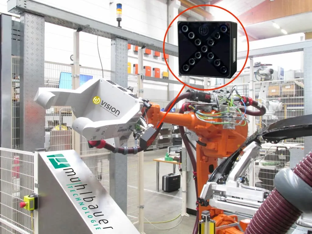
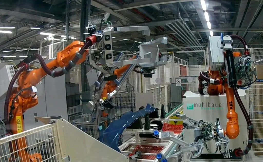
Daylight through a skylight, a hall lamp that is switched on at night, a forklift’s warning light – they all create highlights that come and go. An enclosure or booth removes them and makes the result reproducible around the clock. The Mühlbauer bumper inspection systems use closed booths for exactly this reason: constant light regardless of the time of day or the hall lighting.
Where an enclosure is not possible, a narrow-band light source with a matching band-pass filter in front of the lens suppresses much of the ambient light.
3. Prefer large, diffuse light sources
A small, bright lamp creates a small, saturated highlight. A large, diffuse source – a dome, a diffuser panel, a ring light with a diffuser foil – spreads the same light over a wide range of angles. The highlight becomes larger but much weaker, and the camera can still see the surface through it.
The trade-off: large diffuse light reduces contrast on fine features. For 3D measurement on glossy parts, that is usually a good trade. We also supply lighting hardware for LumiScan cells.
4. Use polarisation deliberately
Specular reflection largely keeps the polarisation of the incoming light; diffuse scattering scrambles it. With a polariser on the light and a second, crossed polariser on the lens, much of the mirror component is filtered out. This works well on paint, plastics and films.
On bare metal, the diffuse component is weak to begin with, so after filtering the image becomes dark – plan for longer exposure or stronger light. Polarisers also cost light in every case, which matters for short exposure times on moving parts.
5. Extend the dynamic range with several exposures
When a part is bright and dark at the same time, no single exposure captures both. Merging several images taken at different exposure times keeps detail in the highlights and in the shadows. In the Mühlbauer project, several images are merged for highly reflective and dark parts.
The price is time: each additional exposure adds to the cycle. Use it where the part requires it, not as a default.
6. Add texture where the surface has none
A light-field or stereo camera needs something to recognise. Glossy parts usually offer enough: machining marks, edges, holes, print. Smooth, matte, single-coloured surfaces do not. For those, a projector casts an artificial random pattern onto the scene. The optional LumiScan SL projector does exactly this for LumiScan X.
On glossy areas, a projected pattern helps far less – it is mirrored away from the camera. Projection is a tool for featureless matte surfaces, not a fix for gloss.
7. Choose the camera position and mounting
- Fixed above the scene: fastest, because the camera can capture while the robot moves. Best when the parts and lighting are well controlled.
- On the robot: the camera can choose its viewpoint per pick and take a second image from another angle when a part is ambiguous – valuable on reflective parts. The Teledyne visual clamping demonstration shows how a measurement path is adapted to wherever the part was placed.
8. Keep it clean
Dust, oil mist and fingerprints on the camera window create a haze that lowers contrast in every image. Define a cleaning interval and make the window easy to reach.
In short
Control the light first, then the exposure, then add texture where needed – and use a camera that looks from many viewpoints so that the remaining highlights can be recognised as what they are. What each 3D method contributes is compared in 3D sensing methods for reflective parts; how to verify the result with your own parts is described in our feasibility checklist.
Frequently asked questions
What is the most effective lighting measure for shiny parts?
Getting the geometry right and taking ambient light out: no lamp or window in the mirror direction of the large surfaces, and an enclosure or booth where daylight and hall lighting change. Both cost little compared with what they gain.
Does polarisation work on bare metal?
Partly. Crossed polarisers suppress the mirror component, because specular reflection keeps the polarisation while diffuse scattering scrambles it. On bare metal the diffuse part is weak to begin with, so the image gets darker. Polarisation works best on paint, plastics and films.
When does a pattern projector help?
On smooth, matte, single-coloured surfaces that offer the cameras nothing to recognise. On glossy areas the projected pattern is mirrored away from the camera, so a projector is no cure for gloss.
Do several exposures slow down the cycle?
Yes, every additional exposure adds time. Use exposure bracketing where a part is bright and dark at the same time, not as a default for every image.
Do I always need an enclosure?
No. If the ambient light is stable, careful placement of the lighting may be enough. Where it changes – skylights, hall lights switched on at night – an enclosure makes the result reproducible. A narrow-band light source with a matching band-pass filter is an alternative.

PD Dr. Christoph Garbe
Christoph Garbe co-founded HD Vision Systems in 2017 and leads the company. As a Privatdozent (associate professor) at Heidelberg University (IWR), he heads a research group for image processing.