The use of robots in industry has many advantages. Their utilization speeds up processes, makes them more precise and allows plants to run 24/7. In order to integrate robots into a production line, plant engineers are forced to build up missing robot knowledge in-house or buy it in externally. Important questions here are: Which robot is the right one? Who can commission the robot? How many robots can be used? A lack of robot know-how can be compensated for by programming via a programmable logic controller (PLC), eliminating the need for tedious coordination between robot specialist and programmer.
How is a PLC structured?
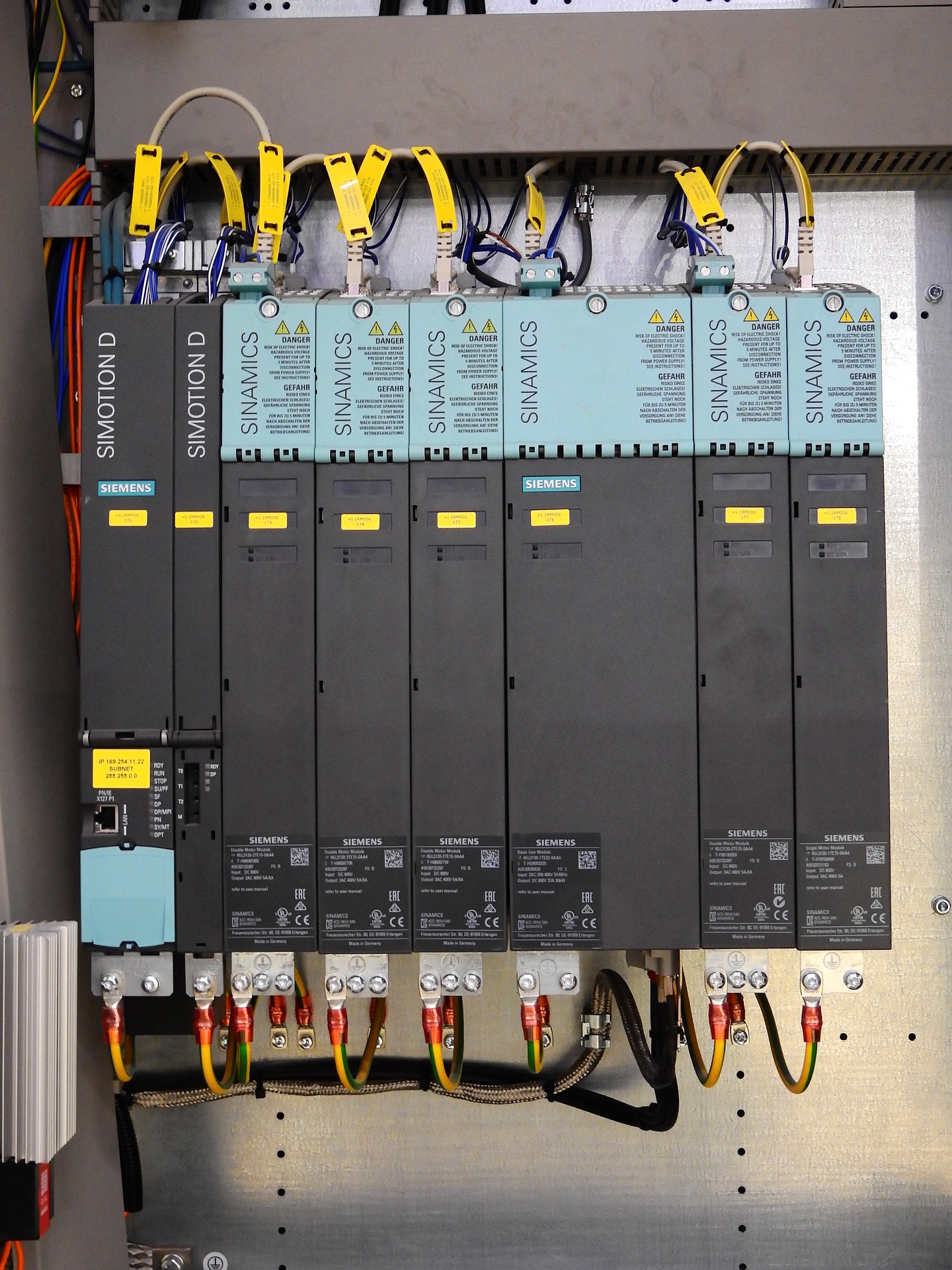
PLC is a program (programming) component to regulate or control a plant or machine. This makes it easy to carry out repeatable processes such as controlling an automated production line, traffic lights or a sewage treatment plant. A PLC consists of inputs, outputs, an operating system (firmware) and an interface through which the user program can be loaded.
The user program determines how the outputs are to be switched depending on the inputs. The operating system, on the other hand, ensures that the current status of the encoders is always available to the user program. With this information, the user program switches the outputs so that the system functions in the desired way. Sensors and actuators are used to connect the PLC to the machine or plant. Sensors are connected to the inputs of the PLC and communicate what is happening in the machine or plant. Examples are:
- Images/point clouds,
- push-buttons,
- light barriers,
- Incremental encoders (sensors to detect the change in position or angle),
- limit switches,
- temperature sensors, or
- level sensors.
Actuators, on the other hand, are connected to the outputs and provide the ability to control the machine or system. Examples of these are:
- Contactors for switching on electric motors,
- electric valves for hydraulics or compressed air, or
- modules for drive control.
Sensors and actuators are increasingly connected to the PLC via field bus rather than discretely. This reduces the wiring effort enormously.

Structure of a PLC
Challenges without PLC
Without a PLC, there are two categories from a developer’s perspective: Robot programmers and software programmers. Both teams develop the respective sequence programs for their sections, as well as human-machine interfaces. Through these visualizations it is possible to operate the plant sections.
Despite the high availability of the system, malfunctions and thus plant downtimes can occur from time to time. As a rule, a user company has little robot know-how, but often a maintenance team with PLC programming experience. If the plant operator is not able to locate the fault himself and thus eliminate the malfunction, he first calls in the company’s internal maintenance department for help. However, if they are unsuccessful, the company must order an external robot specialist. Under certain circumstances, this can mean a longer plant shutdown and thus a production stoppage.

Unclear responsibilities and a lack of agreement often hinder the search for the cause of the error. Friction occurs not only during the project planning, programming and commissioning phases. During warranty, too, separate teams often lead to additional work, which ultimately reduces efficiency.
Even if a plant supplier has found a suitable partner with robot know-how who also provides good support in the event of an incident, this is not enough. Another customer demand also leads to new challenges: Customers demand more flexibility in the selection of the robot manufacturer.
Robot programming with PLC development environment
The solution is a PLC
Two customers have a bin picking problem to solve, but they are working with robots from different manufacturers. As a result, the development environments of the two projects differ significantly. To solve this problem, a plant supplier would either need different robot specialists for both customers or use a PLC.
With the PLC, the plant supplier is able to program the robot himself in a familiar PLC development environment using a robot command library. He still needs help with planning (selecting the right robot), as well as with basic commissioning (installing robot software, setting up the workspace, measuring the tools). However, this effort is relatively small, both in terms of time and cost.
With the PLC, the system supplier themself takes over the commissioning of the system. There is no need to program the interfaces between the robot and the software, and only one programming team is required. You can independently insert several robots from different manufacturers into the sequence without any problems.
If the system stops now and the system operator does not find the error themself, they only have to order the maintenance. This can connect to the PLC programmer and is able to debug both the robot program and the entire periphery of a PLC development environment. This allows production to continue faster and prevents production downtime.
New challenges
Another challenge is path planning. In most cases, this is not done by the PLC programmer, since deeper mathematical knowledge is required. The PLC simply sends commands to the controller, where they are translated and executed. PLC and robot controller are connected via a field bus. This is used for communication and thus for the transfer of data between the two control systems. Examples of this are the Ethercat, Profinet and Enternet/IP protocols. Here, the field bus transmits so-called command IDs, with parameters of the PLC (robot index, speed, acceleration), to the robot.
Concatenation of robot movements
A robot track usually consists of several positions, i.e. several movements. If each individual position is approached individually and linearly, the result is a choppy, jerky sequence. To make the motion more fluid, the following options are available:
- use PTP movements
- loop over points
- chain commands
With a PTP control (Point to Point), the start and end points of a movement are exactly defined. However, the path between the points is not defined in the program. PTP is a comparatively simple and fast control method.
Looping means that a point is not approached exactly, but it is only used as a reference point for the movement. This point then determines a defined distance at which the robot travels an arc. This results not only in a smoother movement, but also in a higher speed.
Command chaining means writing the commands into a buffer of the robot. This allows over-looping to be calculated in advance of a movement. To chain two commands together, the Execute input of the subsequent command is linked to the Busy output of the first command.
Easy day-to-day work thanks to PLC
Despite some challenges in path planning for the robot, a PLC makes the everyday work of a plant engineer much easier. He only needs one programming team and is no longer dependent on the help of many specialists.


